


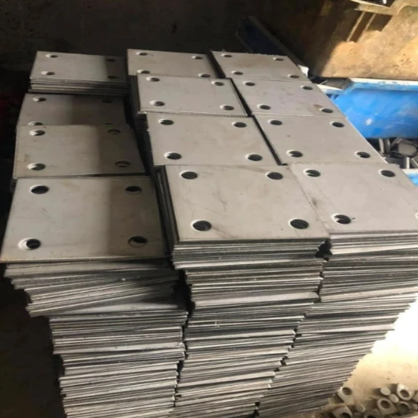
We produce a complete range of structural steel splice plates for beam-to-beam, column-to-column, and truss chord connections. Our product line covers four connection methods - bolted bearing-type, bolted slip-critical, welded, and hybrid - across all standard steel grades from Q235B to Q390, A36 to A709, and S275 to S460. Whether your project calls for standard bolted flange splices for a warehouse portal frame or fatigue-rated slip-critical splices for a crane girder, we have the production capacity and technical capability to deliver.
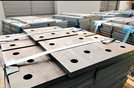
When Are Splice Plates Needed?
| Scenario | Explanation |
|---|---|
| Member Length Exceeds Mill Capacity | Standard steel sections (W-shapes, H-beams) are typically available in 12-18m lengths from mills. For longer spans, members must be spliced. |
| Transportation Limitations | Truck/trailer transport typically limited to 12-13m (standard) or 18m (extended permit). Members exceeding these lengths must be spliced on-site. |
| Column Base-to-Shaft Transition | Multi-story buildings use thicker/heavier column sections at lower floors and lighter sections above - spliced at floor levels. |
| Erection Sequence Requirements | Complex structures may require members to be installed in sections due to crane reach, site access, or construction sequencing constraints. |
| Future Modifications or Extensions | Bolted splice plates allow for future disassembly, modification, or extension of the structure - critical for modular and adaptable designs. |
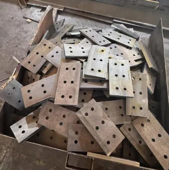
Specifications of Structural Steel Splice Plates
| Parameter | Specification | Standard / Code |
|---|---|---|
| Steel Material Grade |
Q235B / Q345B / Q390 (CN) A36 / A572 Gr.50 / A709 Gr.50 (US) S275 / S355 / S460 (EU) |
GB/T 700, GB/T 1591, ASTM A36/A572/A709, EN 10025 |
| Plate Thickness | 6mm – 80mm | GB/T 709, ASTM A6 |
| Plate Dimensions | Length: 200mm – 3000mm; Width: 100mm – 1200mm | Per project drawings |
| Connection Type | Bolted (bearing / slip-critical) / Welded / Hybrid | AISC 360 Ch. J, EN 1993-1-8 |
| Bolt Grade | 8.8s / 10.9s , A325 / A490 , 8.8 / 10.9 | GB/T 1231, ASTM F3125, EN 14399 |
| Surface Treatment | Sa 2.5 + epoxy primer / HDG / fire coating | ISO 8501-1, ASTM A123, EN ISO 12944 |
| Design Code | AISC 360-22, EN 1993-1-8, GB 50017-2017, AS 4100 | Project-specific |
Splice Plate Types We Manufacture
We manufacture splice plates for all major structural joint types. Each type we produce is engineered to meet specific load transfer requirements, fatigue performance, and erection conditions per your project design code.
By Member Type
| Splice Type | Application | Our Plate Configuration |
|---|---|---|
| Beam Splice Plates | Splicing beam segments at lower-moment points (1/4 to 1/3 span) | We fabricate flange splice plates (top & bottom) + web splice plates; or full-depth splice plates per your drawings |
| Column Splice Plates | Multi-story column transitions; same/different section splicing | We provide flange splice plates (4 sides) + web filler plates; or butt-welded with backing |
| Truss Chord Splice Plates | Truss top/bottom chord splicing; space frame member connections | We fabricate gusset plate splices, bolted flange splices for H-section chords, tubular splice sleeves |
| Crane Girder Splice Plates | Crane runway girders subject to fatigue from moving loads | We fabricate slip-critical bolted splices only (no welded tension flange); designed per fatigue category |
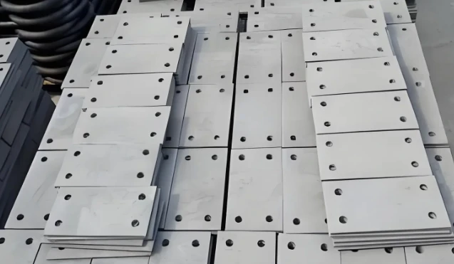
Roles of Structural Steel Splice Plates
Realize Member Extension
When the designed length of steel beams, steel columns or webs exceeds the maximum fixed length of rolled steel products, splice plates are used to connect two or multiple steel segments together.
01
Transfer Internal Forces and Loads
At butt joints, via welds or high-strength bolts between splice plates and primary members, splice plates smoothly transfer tension, compression, shear force and bending moment from one disconnected segment to the other, ensuring continuous force transmission of the whole structure.
02
Boost Sectional Resistance
Additional steel plates installed at weak sections or joints compensate for bearing capacity loss caused by section weakening or disconnection, and even locally enhance structural stiffness.
03
Reduce Stress Concentration and Deformation
During factory prefabrication or field assembly, segmented splicing combined with rational layout of splice plates can effectively adjust and release welding residual stress, controlling the overall structural deformation.
04
Facilitate Transportation and Lifting
Extra-long and oversized members cannot be shipped as a whole. Segmented fabrication followed by field assembly with splice plates lowers logistics and construction difficulties.
05
Applications of Structural Steel Splice Plates
Industrial Buildings
Workshops, warehouses, factory frameworks - beam and column splices for portal frames, crane girder splices.
Bridges
Highway and railway bridges - girder splices, truss chord splices, cross-frame connections designed for fatigue.
High-Rise Buildings
Multi-story steel frames - column splices at floor levels, beam splices at moment connection points.
Power & Energy
Power plants, substations, transmission towers - structural member splicing for equipment support frames.
Large-Span Structures
Stadiums, arenas, exhibition halls, airports - truss chord splices, space frame node connections.
Marine & Port
Port crane structures, offshore platforms, wharf frameworks - splice plates with HDG or C5-M coating.



Steel Grade Selection Guide for Splice Plates
Choosing the right steel grade for your splice plates affects both cost and performance. The splice plate material should match or slightly exceed the parent member's yield strength.Below is our practical guide of fabrication across global projects:
| Parent Member Steel | Recommended Splice Plate | Yield Strength | Typical Project Type |
|---|---|---|---|
| Q235B / A36 / S275 | Q235B / A36 / S275 | 235 / 250 / 275 MPa235/250/275 MPa | Standard warehouses, low-rise buildings, non-critical structures |
| Q345B / A572 Gr.50 / S355 | Q345B / A572 Gr.50 / S355 | 345 / 345 / 355 MPa345/345/355 MPa | Industrial buildings, bridges, high-rise frames, crane girders |
| Q390 / A709 Gr.50 / S460 | Q390 / A709 Gr.50 / S460 | 390 / 345 / 460 MPa390/345/460 MPa | Long-span bridges, heavy industrial, seismic structures |
| Weathering Steel (Q355NH / A588) | Q355NH / A588 (matching) | 355 / 345 MPa355/345 MPa | Unpainted bridges, architectural exposed structures |
Note:We source all plate steel from Tier-1 Chinese mills - Shougang, Baosteel, and Ansteel. Every batch arrives with EN 10204 3.1/3.2 Material Test Reports. If your project requires specific mill certification (e.g., Ansteel for Australian projects, Baosteel for Middle East), we accommodate that request.
Our Quality Control
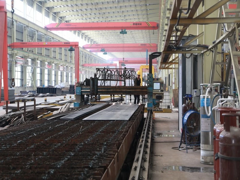
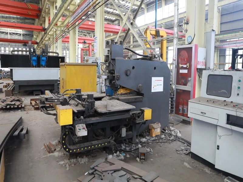
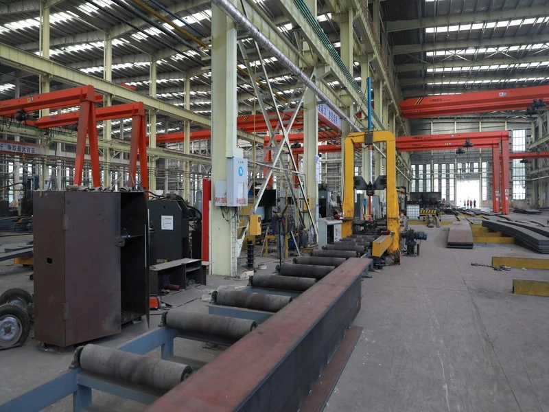
Every splice plate we ship passes through a multi-stage QC checkpoint system - from raw material verification to final coating inspection. Below is what we check, what we certify, and what documentation you receive with each order:
| Stage | Checkpoint | What We Verify | Record Issued |
|---|---|---|---|
| ① | Incoming Material | Mill cert cross-check vs. heat number; thickness measurement; surface defect visual | Material Receiving Report + MTR filing |
| ② | CNC Drilling | Hole position ±1.5mm; hole diameter vs. bolt grade; edge distance compliance | First Article Inspection (FAI) Report |
| ③ | Welding (if applicable) | WPS compliance; welder qualification; visual weld profile; 100% UT on full-pen welds | Weld Map + UT Report (ISO 17640) |
| ④ | Dimensional Verification | Length, width, thickness, flatness, hole pattern per AWS D1.1 / EN 1090-2 tolerances | Dimensional Inspection Repor |
| ⑤ | Surface Treatment | Sa 2.5 surface profile; coating thickness (elcometer); HDG coating weight | Coating Thickness Record |
| ⑥ | Final Release | Compile QC Dossier; cross-check all records; pack with identification tags | Project QC Dossier (complete package) |

How to Order - Simple 4-Step Process
Send Drawings
Email us your structural drawings, load specs, design code, and required quantity. We review within 24 hours.
Receive Quote
We provide a detailed quotation with material breakdown, fabrication timeline, and total price - including any design optimization suggestions.
Approve & Produce
After your drawing approval and deposit, we begin fabrication. You receive weekly progress photos and QC updates.
QC & Ship
Final QC, third-party inspection (if required), packaging, and shipping with complete documentation dossier.
Note:To get the fastest and most accurate quotation, please include:
(1) Structural drawings showing splice locations;
(2) Member sizes (W-shape, H-section, etc.);
(3) Design code (AISC, EN, GB);
(4) Bolt grade and diameter;
(5) Surface treatment requirement;
(6) Total quantity and delivery deadline.
FAQ:
What is the difference between a splice plate and a gusset plate?
A splice plate joins two collinear members end-to-end to extend their length or transition between sections. A gusset plate connects multiple non-collinear members at a joint (e.g., truss node where diagonals, verticals, and chords meet). Splice plates transfer forces along the member axis; gusset plates transfer forces between members at different angles.
Should I use bolted or welded splice for my project?
It depends on load type, erection method, and inspection access. Bolted splices (especially slip-critical) are preferred for dynamic/fatigue loads, field conditions, and future disassembly. Welded splices are preferred for architectural (no visible bolts), rigid moment connections, and shop-fabricated splices. Many projects use hybrid: shop-welded flanges + field-bolted webs.
Can splice plates be galvanized?
Yes. Hot-dip galvanizing per ASTM A123 is a common surface treatment for splice plates in corrosive environments. However, for slip-critical connections, the galvanized faying surface has a lower slip coefficient (Class C, μ=0.20) compared to blast-cleaned steel (Class A, μ=0.33). This must be accounted for in the design - more bolts or larger plates may be needed.
Where should beam splices be located?
Beam splices are typically located at points of lower bending moment - approximately 1/4 to 1/3 of the span from the support, where moment is roughly 50-75% of the peak. Avoid splicing at midspan (maximum positive moment) or at the support face (maximum negative moment) unless the splice is designed for full moment capacity.


