


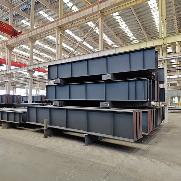
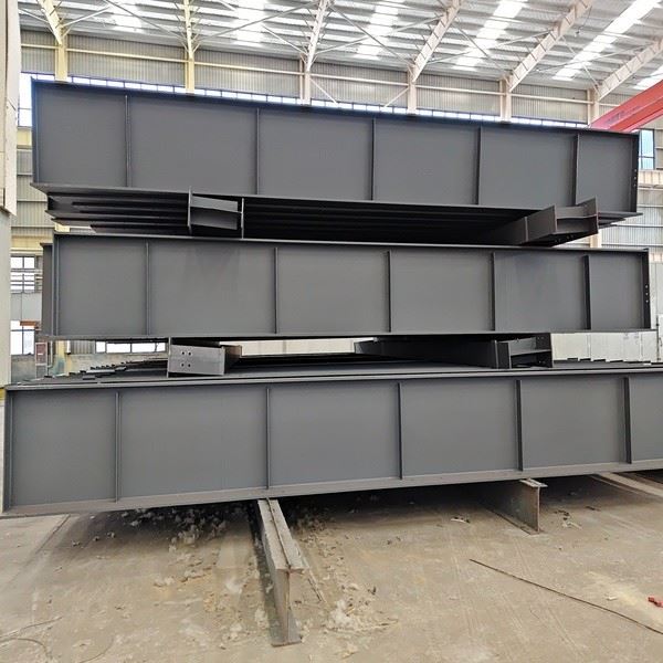
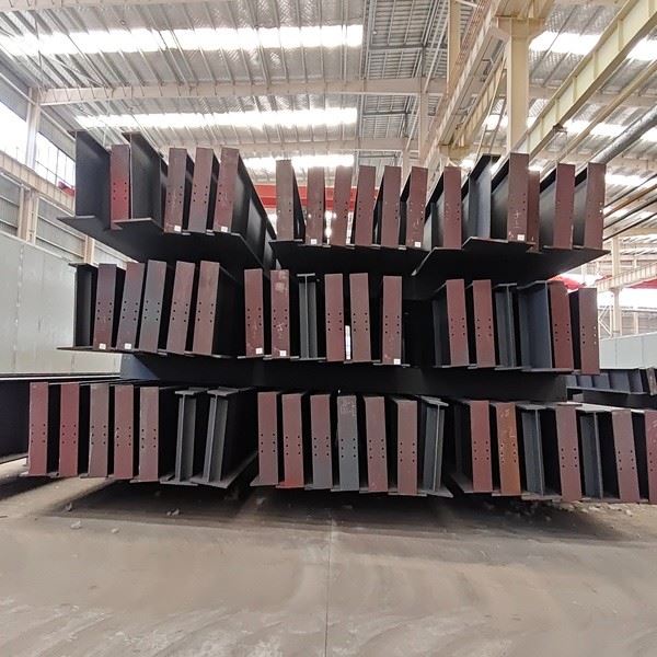
A steel crane girder is the horizontal runway member that carries an overhead traveling or gantry crane and its hoisted load along the length of an industrial building. Because the load rolls on concentrated wheels and cycles millions of times over the girder's life, a crane girder is far more demanding than a normal floor beam: it must resist fatigue, dynamic impact, biaxial bending and web buckling, not just static weight.
Our heavy-duty crane girders are engineered to sustain these repeated crane loads for 24/7 industrial operations, fabricated to AISC 360 and Eurocode 3 (EN 1993) with precision camber control and full-penetration welding on the top flange, so the running track stays level, the weld stays crack-free, and the mill, workshop or warehouse runs without unplanned downtime. We supply simply-supported, continuous and truss-type girders in Q355, S355 and ASTM A572 Gr50/60, with 100% ultrasonic NDT, material certificates and third-party inspection available, quoting within 24 hours.

Types of Crane Girders
Simply Supported Crane Girder
Features: Supported on steel columns at both ends. Easy to construct with definite force distribution.
Application: Widely used for spans of 6 to 12 meters and light-capacity cranes; it is the most popular type on the market.
Continuous Crane Girder
Features: Designed as multi-span continuous structure with even stress distribution. It enables smaller beam sections and material savings, yet involves higher construction difficulty.
Application: Mainly adopted in large-span and heavy-load workshops such as metallurgical plants and heavy machinery factories. Its application scope is relatively limited.
Truss-type Crane Girder
Features: Truss structure effectively reduces self-weight, while the overall construction is complicated.
Application: Ideal for ultra-long-span projects.

Specification of Crane Girders
| Item | Specifications |
| Description | Structural Steel Crane Girders |
| Material Grade | Q355B/C/D/E, S355JR/J0/J2, ASTM A572 Grade 50/60 |
| Standard | AISC 360, Eurocode 3 (EN 1993), ASTM A6, AS/NZS 3678 |
| Welding Process | Automatic Submerged Arc Welding (SAW), CO2 Gas Shielded Welding |
| Quality Control | 100% NDT (Ultrasonic Testing), Magnetic Particle (MT), Camber Measurement |
| Application | Heavy Industrial Workshops, Logistics Centers, Shipyards, Power Plants |
| Surface Finish | Shot Blasting Sa 2.5 + High-performance Epoxy Coating or Hot Dip Galvanizing |
| Packing | Heavy-duty Steel Cradles & Secure Lashing for Global Maritime Export |
Roles & Advantages of Crane Girders
Role of Crane Girders
Load transmission - steadily transfers the crane lifting load, self-weight and dynamic impact loads to the steel columns and foundations.
Precision guarantee - provides a stable running track for the crane to ensure accurate lifting operations.
Advantages of Crane Girders
High load-bearing capacity & large span - steel offers far higher strength than concrete, meeting large-span workshops and heavy-duty cranes.
Fast construction & cost saving - all components are prefabricated in the factory; easy on-site installation shortens construction and cuts labor costs.
Excellent seismic performance & recyclability - steel has high toughness and outstanding seismic resistance, and can be recycled after demolition.

Applications of Crane Girders
Industrial Manufacturing:Production lines for heavy machinery and equipment assembly.
Warehousing & Logistics:High-capacity storage facilities for moving steel coils and pallets.
Power & Energy Plants:Installation and maintenance of turbines and generators in power halls.
Shipbuilding & Metallurgy:Assembly of hull sections and transport of molten metal in steel mills.
Aircraft & Rail Maintenance:Engine lifting and heavy component maintenance in hangars and depots.

Recommendations for Crane Girders Installation
1.Pre-installation Inspection:Verify component dimensions and weld quality prior to installation. Remove debris from column corbels and ensure full contact surfaces are flat and clean.
2.Strict Control over Lifting & Alignment Accuracy:Use a level instrument to calibrate the elevation of crane girders. The allowable deviation of the centerline axis is ±3 mm, and the surface flatness tolerance shall not exceed 5 mm per 2 meters, to prevent crane derailment during operation.
3.Secure Fixing & Final Acceptance:Check verticality after temporary fixation. Apply anti-corrosion treatment upon completion of welding. Conduct load tests to verify overall performance. The beams can only be put into service after passing all inspections.

Our Quality Control
We conduct rigorous testing and inspection throughout the fabrication of structural steel components for crane girders to ensure full quality control.

Material Inspection
Chemical composition & mechanical property testing

Weld Inspection
100% non-destructive testing (NDT) to ensure nracks or porosity


Load Testing
Simulated stress condition testing
Packing & Transportation
| Item | Detail |
|---|---|
| Packing | Girders secured on heavy-duty steel cradles or skids with steel lashing, weld zones and edges protected. |
| Transport | Flat-rack, open-top container or break-bulk loading engineered to girder length with stable sea stow. |
| Lead time | Shop order 15–30 days. |
| Marking | Section, steel grade, length and bundle/unit mark per the drawing. |
| Docs shipped | Packing list, invoice, MTC, NDT/inspection reports and shop drawings. |
FAQ:
How is a crane girder connected to the column and to the rail?
Each girder end rests on a steel corbel or column-top bearing, fixed with anchor bolts or high-strength bolts so verticality and centreline can be trued before final tightening. On top, the crane rail is seated on a rail pad and held down by rail clips or clamps - not welded directly - so it can be adjusted for line and level. Tell us your column arrangement and rail section and we detail the bearing and clip layout.
What element accuracy and camber is guaranteed?
We set precision camber to offset dead-load deflection, then verify it in QC. Site alignment targets are roughly: girder centreline ±3 mm, top-flange surface flatness ≤5 mm per 2 m, and rail top elevation to the level you specify.
Is the top-flange weld fully penetrated, and how are weld classes chosen?
The loaded top flange uses full-penetration welding for maximum fatigue resistance, while lighter appendages may use partial-penetration or fillet welds designed to a fatigue detail class. Every weld then passes 100% UT, with MT on critical zones; a higher detail category is chosen where the duty class demands it.
What happens when a girder is longer than transport or workshop limits?
Long girders are fabricated in segments that are spliced on site with high-strength bolts or a shop-prepared welded joint. Splice positions are located at the lowest bending moment and checked for fatigue, so the assembled girder behaves like a continuous member.
Do you provide shop drawings and design coordination?
Yes. We model in Tekla, issue fabrication and assembly drawings, and coordinate the bearing elevation, anchor-bolt plan and rail fixing with your frame design so corbels, columns and the runway line up before steel arrives on site.
What is your maximum fabricated size, capacity and lead time?
Fabrication is limited by our shop crane reach and lifting capacity, and by head-room at the port; typical output and lead time are sized to your order once the span, duty class and quantity are confirmed.


